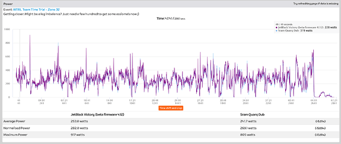
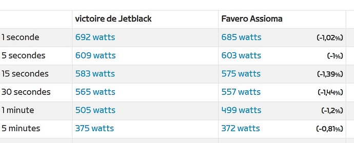
I’ve had some time to think about this and test different things, and I’ve come to a similar conclusion. Please prepare yourself for armchair engineering…
Resistance on the trainer comes from two sources:
- Rolling resistance from the belt, bearings, freewheel, etc.
- Braking resistance from the electromagnetic coils and flywheel (eddy current braking)
Rolling resistance changes as the bearings and belt heat up, and spindowns currently occur with no resistance as far as I’m aware, so temperature compensation then is only accounting for rolling resistance.
Braking resistance is more complicated and is a function of voltage applied to the coils (magnetic field strength), design of the coils (number of turns, etc.), electrical conductivity of the flywheel (probably affected slightly by temperature changes), rotational velocity of the flywheel (measured with optical sensor and target, so controlled), and air gap distance between the coils and flywheel (largely controlled by manufacturing process, but could change due to thermal expansion). Since the spindown is done with no braking resistance, there is no calibration or compensation for changes. Voltage applied to the coils and design of the coils should never really change and the rotation velocity is accurately tracked, so there’s no need for calibration for those parameters. Electrical conductivity and air gap distance probably change slightly as the unit heats up, and this is why watts drift up during use (air gap at the very least should increase as the unit heats and the shaft/spacer expand and push the flywheel away from the coils).
Worth noting is that braking resistance is inversely proportional to air gap distance, and the distance on mine is already 1 mm or less (you can see the squares from the coils if you look through the gap between the flywheel and the plastic shroud). What this means is that a very slight change in gap distance can have a pronounced effect on braking resistance.
Wild assumptions ahead, but if gap distance is 1 mm, then a 0.01 mm change in gap distance yields a 1% change in power. For reference, a sheet of paper is ~0.1 mm thick (10% change in calculated braking resistance vs actual braking resistance). You can imagine how the slightest of movement, either due to thermal expansion or movement due to shipping practices could affect the accuracy of the unit. I’m especially concerned that shipping during the stressful holiday season could open the opportunity for mishandling of the unit which could cause subtle changes in the air gap distance between factory calibration and delivery. In other words, the flywheel and shaft basically act like a slide hammer, so if the package was dropped on its side (not an uncommon practice for FedEx), then the fly gap distance might be “adjusted”.
Since power is calculated as the sum of rolling resistance (linear increase with flywheel velocity) and calculated braking resistance (voltage applied, coil design, linear increase with flywheel velocity, and an assumed, fixed air gap distance and flywheel electrical conductivity), you can see where the error could come from. Especially important is the shipping “adjustment”.
So, what’s the fix? No amount of spindowns as currently implemented will allow for calibration of the braking resistance. What we need is an option for a “factory” or “advanced” spindown that Wahoo uses that does indeed calibrate using braking resistance. Otherwise, you’re putting the fate of accuracy into the hands of FedEx et al. Now, you might get lucky and have just the right “shift” occur to put things closer to factory air gap. I’ve seen other report this happening, and mine seems to have turned a page after ~800 km and some really hard (high heat) efforts.


